| 1. |
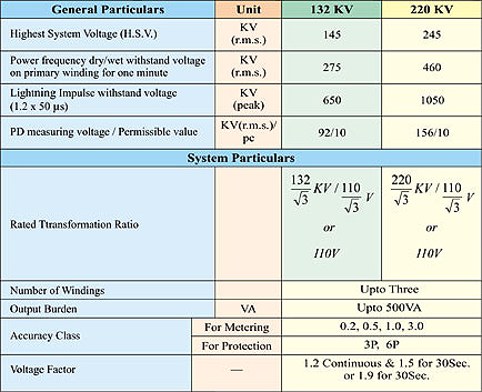
Tank / Top chamber / Base assembly are made of mild steel. Their external surface is painted with one coat of primer and two coats of synthetic enamel paint or hot - dip -galvanized as per customer requirement. Their internal surface is painted with two coats of an oil insoluble paint. |
| 2. |
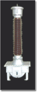
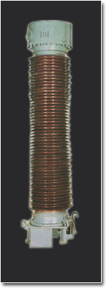
Hollow porcelain insulator conforming to IS: 5621 is mounted over the live terminal end of primary winding and is bolted to the tank in case of 132 KV VT and bolted to the base assembly in case of 220 KV VT. Maximum creepage factor of insulator shall be 3.5 for light or normal pollution level and 4.0 for heavy or very heavy pollution level whereas the minimum creepage distance in mm / KV of HSV shall be 16 or 20 for light or normal pollution level and 25 or 31 for heavy or very heavy pollution level respectively. |
| 3. |
Primary winding consists of dual coated synthetic enamel round copper wire in suitable alternate of wire and insulating Kraft paper. It is wound in pyramid construction to have the voltage stress graded uniformly. Insulation paper is folded over the winding to make the unit compact and to insulate the winding from core & housing etc. Primary winding of 132 KV VT is in single stage whereas that of 220 KV VT is in the cascaded four stages. The live end of the primary winding is connected to top chamber fitted to the top of the insulator. |
| 4. |
In 132 KV VT, the secondary winding is placed over the core limb prior to the tank forming the lower part of the transformer. In 220 KV VT, the secondary winding is placed on the primary winding of the last stage and the core- coil assembly of all the windings of the cascaded four stages is housed in the hollow insulator. Secondary terminals are brought out in the secondary terminal box on the side of the tank in case of 132 KV VT and on the side of the base-assembly in case of 220 KV VT. |
| 5. |
Insulation of VT is dried out by heating in vacuum. Dried and degassed oil conforming to IS:335 is then filled in the transformer under vacuum. |
| 6. |
Di-electric strength of the oil-impregnated paper insulation is preserved by hermetic sealing of the transformer. Expansion and prevention of oxidation of oil are taken care by filling dry nitrogen above oil in the nitrogen chamber at atmospheric pressure. All the gasketed joints are located below oil level to ensure positive sealing. |
| 7. |
Each transformer undergoes all the routine tests before dispatch and is delivered safe at site in duly packed condition. However, few precautions are to be observed as follows :- |
| |
| I |
Transformer is to be unpacked fully and made to stand vertical before carrying out any site tests including measurement of IR value by megger. Store the transformer vertically. |
| II |
Before energizing, one terminal of all the secondary windings not being used is to be grounded. |
| III |
Primary connection is to be tightened sufficiently to avoid hot connection. |
|
| 8. |
As the transformer is hermetically sealed, normal maintenance comprise of only visual
inspection to check oil level and possible oil leaks besides cleaning insulator surface
periodically depending on the pollution level existent at site. |